Garrattfan's Modelrailroading Pages

NS 8600 class
Preparing the chassis

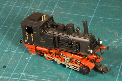
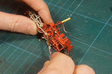
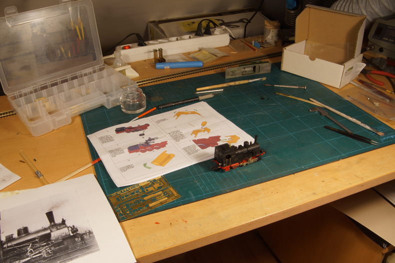
My workbench at the start of the project, the Fleischmann T3 waiting to be butchered. The chassis should be a doddle. Basically you only have to remove the couplers, lift out the cylinders and the motion gear, add a few etched parts, reassemble and paint. Well, it proved to be a bit more complicated. Because this is a kit for beginners, I will also write for beginners so I will elaborate on the problems that arose and how I solved them. The more experienced builder may just glance through the photos to understand. |
|
 |
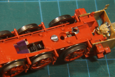
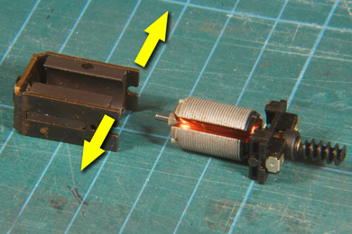
Disassembling any ready-to-run locomotive may prove a challenge because suppliers are increasingly ingenious to hide the actual construction of the model in preference of a prototypical look. So clips and screws tend to be in very in very obscure places. It is always a wise thing to nose around on the internet before commencing. It proved to be simple this time with only one conspicuous bolt to be undone at the bottom of the model. The model is then turned around and the chassis is carefully lifted from the front over the cast clips on the back. As simple as that. |
 |
 |
 |
The cylinders are clipped on and can be removed by a little wriggling to and fro. The motion gear is made of a rather soft plastic and will bend sideways when the cylinder comes afield. As soon as the cylinder clear its stud you can carefully pry the motion out of the hole in which it sits in the cylinder. |
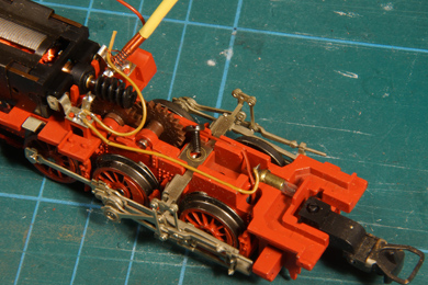 |
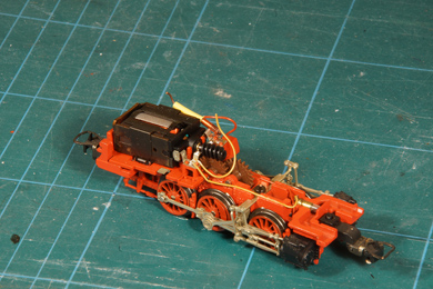
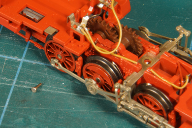
Now I needed to get the motion gear off the chassis. The photos show that the wiring to the front lamp is in the way. When I bought this model it had some sort of electronics (DCC-chip?) installed by the previous owner and I had already clipped that out. The wiring was a mess since then and I left it to be tended to once I got to build the model. Well, that was now and I had no clue how the wiring was to go. That is of course one of the setbacks of buying a non-working model from a scrapbox: there is a reason why it does not work! Wiring could be one of those reasons. If you want to start without such trouble buy a working second hand. They are available on eBay for about 60-80 Euro. |
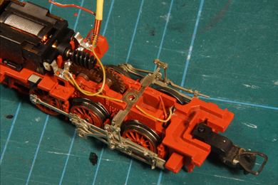 |
I got fed up with studying the wiring and decided to take my chances and completely rewire the model myself. I removed the headlamp bulb and simply clipped the wiring that was in the way. |
 |
The motor could be removed by detaching the the motor clip from the underside with a screwdriver. The motor now simply falls out. |
 |
 |
 |
 |
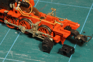
| To lift the motion gear the crankpins have to be taken out. They are press fit in the wheel face so with some persuasion with a screwdriver behind the coupling rod they will come loose. Once that is done you can start adding the parts the kit to elongate the chassis at the front end. | |
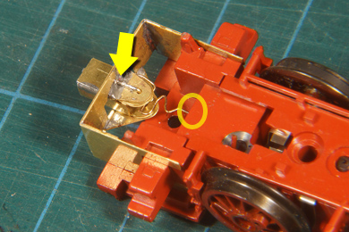 |
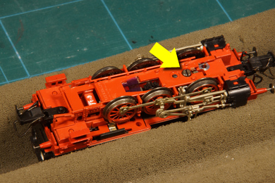
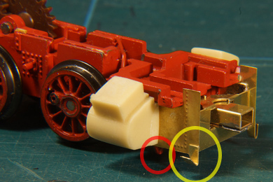
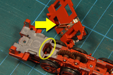
I made this elongation as per the instructions of the kit (numbers 6, 7, 8, 9). A small piece of phosphor bronze wire form a spring which controls the coupling. I drilled a small hole in the frame in which the phosphor bronze wire is inserted (yellow circle). The coupling revolves around a piece of brass wire of which the end was angled and soldered on the stationery part of the coupling shaft (arrow). |
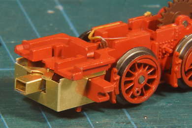 |
On top side I simply clipped this brass wire off. The assembly is glued in place with 5 in two component Epoxy (I use Bison Kombi Snel epoxy which holds about 300 kg/cm2) |
 |
Preparing the cylinder castings is easy. It is reasonably free from flash so removing it needs little attention with a sanding stick. The holes to take up the driving rod and the valve needed to be drilled out to 2.7 and 0.8 mm respectively |
 |
Then I added the riveted sheets. Again I glued them with 5 min epoxy. The rail cleaners (yellow circle) were folded over completely and soldered. Be gentle with the soldering iron though. The epoxy glue gives way when heated, so be quick, do not linger with the soldering iron. I also test fitted the cylinders which proved to be some sort of error. When I wanted to remove them again I had a hard time doing so. They get on easily, but are hard to remove again! |
 |
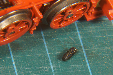 |
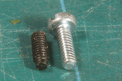
| Again the second hand nature of this loco showed up. There was a stub of a broken plastic bolt in the bottom plate which must have kept the the bottom plate in place in its days. I put a sharp screwdriver on it with some force and made an appropriate slit in the bolt's head. Then I could gently take it out. | |
 |
 |
Fortunately the plastic bolt seemed to match the M2 bolt I had in store and its was quickly replaced.
|
|
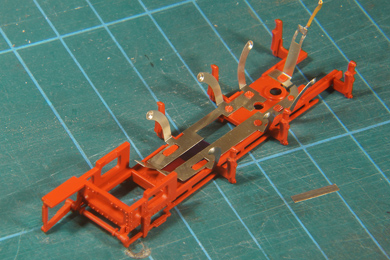 |
I took out the bottom however to see how the wipers and electrical connection would run. After all I had no clue how the electrical wiring of the locomotive used to run |
 |
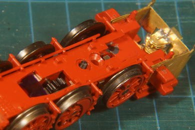
It is relatively easy to see how the electrical connection is made. With the bottom plates in place there are two connectors point upwards (in the yellow circle, they can be seen in on the left hand side on the previous photo). The vertical strips hanging down from the motor plate touch on them when tuned correctly. It takes bit of fiddling to get it done, but basically it is easy. |
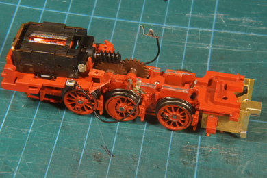 |
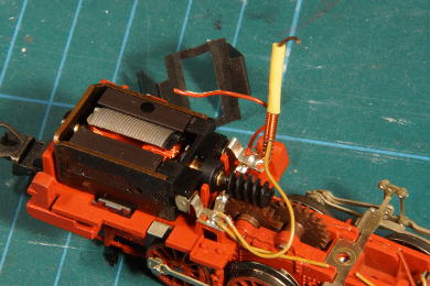
Now rewiring the locomotive starts. One is inclined to carry on with building the locomotive, but I have learned to get the locomotive chassis running in the earliest stage of the project. If the project is to fail, it is better to fail as early as possible, and after all this locomotive being a cheapy from a scrapbox was an unknown factor. And I was right. I clipped the motor into place and it would not run. Unclipped an applied power, run. Clipped back on, power, no run. Now what? Some prodding soon showed that the motor core was stuck once the motor was clipped on, so obviously the clip had a negative effect. The clip pressed on the two motor's magnets and I soon spotted one of them being loose. Once the clip came on the magnet moved away against the motor core. Cause found! |
 |
But what to do about it? Well, after a brief inspection of the open motor construction I found I could open the motor by pulling the U-shaped iron frame apart and lift out the motor core. |
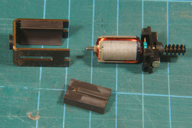 |
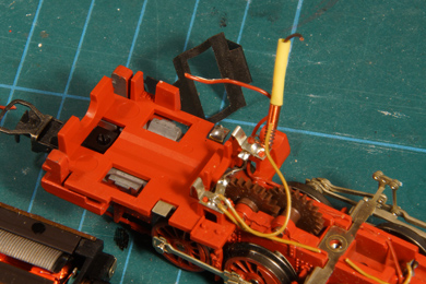
Now I could lift the magnet out, which needed no persuasion whatsoever. I glued it back into place with, again, 5 min epoxy and after setting replaced the motor core. |
 |
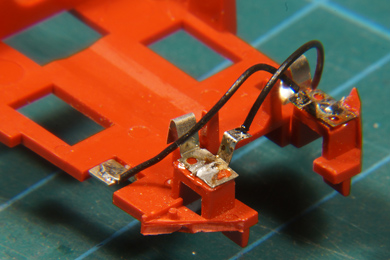 |
| Now the motor could finally be rewired. I simply snipped everything off and layed two new wires from the appropriately provided tabs to the motor tabs. I soldered them to the motor clips and then glued the motor clips back in their places. Now, every locomotive is supposed to run in the same direction. So I have my industry made models as examples to show the right direction. With a given wiring setup and the transformer control knob turned right they all go right, transformer control knob left they all go left. Easy. Of course at first wiring my new model would the wrong way, so had to cross over the wired to get it to run the right way. Later I learned I could alternatively have flipped the motor over, it was simply upside down in place (stupid me). As I did not want to rewire the locomotive again it left as it was. | |

Sign my
GuestBook